Tag Archives: device driver

Fundamentals of PCI device and PCI drivers.

Hello Folks, today i am going to talk about the PCI subsystem and Process of developing PCI based Device driver.

PCI is a local bus standards, which used to attach the peripheral hardware devices with the Computer system. So it defines how different peripherals of a computer should interact. A parallel bus which follows PCI standards is knows as PCI bus. PCI stands for Peripheral Component Interconnect.

The devices which are connected to PCI bus are assigned address in the processor’s address space. This memory(addresses in processor’s address space) contains control, data and status registers for the PCI based  device, which is shared between CPU and PCI based device. This memory will be controlled by the device driver/kernel to control the particular device connected over PCI bus and share information with it. PCI device became  like a memory mapped device.

The PCI address domain contains the three different type of memory which has to be mapped in the processor’s address space.

1. PCI Configuration Address space

Every PCI based  device has a configuration data structure that is in the PCI configuration address space. The length of configuration data structure is 256 bytes. This data structure used by system/kernel to identify the type of device. The location of this data structure is depend upon the slot number where the device is connected on the board. eg. Device on slot 0 has its configuration data structure on 0x00 but if you connect same device on slot 1 its configuration data structure goes to 0xff. You can get more details about layout of this configuration data structure here.

At power on, the device has no memory and no I/O ports mapped in the computer’s address space. The firmware initializes PCI hardware at system boot by mapping each region to a different address. By accessing PCI controller register, the addresses to which these regions are currently mapped can be read/write from the configuration space, By the time a device driver accesses the device, its memory and I/O regions have already been mapped into the processor’s address space.

So To access configuration space, the CPU must write and read registers in the PCI controller. Linux provides the standard API to to read/write the configuration space. The exact implementation of this API is vendor dependent.

int pci_read_config_byte(struct pci_dev *dev, int where, u8 *val);

int pci_read_config_word(struct pci_dev *dev, int where, u16 *val);

int pci_read_config_dword(struct pci_dev *dev, int where, u32 *val);

The above APIs are used to read the different size of data configuration space. The first argument is the pci device node, the second argument is the byte offset from the beginning of configuration space and third argument is the buffer to store the value.

int pci_write_config_byte(struct pci_dev *dev, int where, u8 val);

int pci_write_config_word(struct pci_dev *dev, int where, u16 val);

int pci_write_config_dword(struct pci_dev *dev, int where, u32 val);

The above APIs are used to wirte the different size of data configuration space. The first argument is the pci device node, the second argument is the byte offset from the beginning of configuration space and third argument is a value to write.

2. PCI I/O address space 

This is 32 bit memory space which can be access by using CPU IO access instructions. PCI devices place their registers for control and status in PCI I/O space.

3. PCI memory Address space

This is 32 bit or 64 bit memory space which can be  access as the normal memory locations. The base address of the this memory space is stored in the BAR register. The PCI memory space have higher performance than access to PCI I/O space.

Specification of I/O and memory address is device depended. I/O and memory address can be access by normal memory read write operations.

We have gone through the basic memories region of PCI device. Now its time to understand the different initialization phase of the of PCI devices.

Linux kernel devices the PCI initialization in to three phase.

1. PCI BIOS :  It is responsible for performing all common PCI bus related task. Enable the access to PCI controlled memory. In some CUP architecture it allocate the interrupts for PCI bus.

2. PCI Fixup : It maps the configuration space, I/O space and Memory space to the RAM. Amount of memory for I/O region and memory region can be identified from the BAR registers in configuration space. In some of CPU architecture Interrupts are allocated at this stage. It also scan all the bus and find out the all present devices in the system and create pci_dev structure for each present device on the bus.

3. PCI Device Driver :  The device driver registers the driver with product Id and vendor Id. The PCI  subsystem checks for the same vendor Id and product id in its list of devices registered at the Fixup phase. if it gets the device with same product Id and vendor Id the it initialize the device by calling the probe function of driver which registers further device services.

So, this was just an overview of the how PCI based devices works with the Linux kernel.

Stay tunes !!

7 Comments

Filed under Linux Device Driver

Synchronization mechanisms inside Linux kernel

Hello folks, today i am going to talk about the synchronization mechanism which is available in Linux kernel. This post may help you to choose right synchronization mechanism for uni-processor or SMP system. Choosing wrong mechanism can cause crash to kernel or it can damage any hardware component.

Before we begin, lets closely examine three terminology which will use frequently in this post.

1. Critical RegionA critical section  is a piece of code which should be executed under mutual exclusion. Suppose that, two threads are updating the same variable which is in parent process’s address space. So the code area where both thread access/update the shared variable/resource is called as a Critical Region. It is essential to protect critical region to avoid collusion in code/system.

2. Race Condition: So developer has to protect Critical Region such that, at one time instance there is only one thread/process which is  passing under that region( accessing shared resources). If  Critical Region  doesn’t protected with the proper mechanism, then there are chances of Race Condition.

Finally, a race condition is a flaw that occurs when the timing or ordering of events affects a program’s correctness. by using appropriate synchronization mechanism or properly protecting Critical Region  we can avoid/reduce the chance of this flaw.

3. Deadlock: This is the other flaw which can be generated by NOT using proper synchronization mechanism. It is a situation in which two thread/process sharing the same resource are effectively preventing each other from accessing the resource, resulting in both programs ceasing to function.

So the question comes to mind is “what is synchronization mechanism ?” Synchronization mechanism is set of APIs & objects which can be use to protect critical region and avoid deadlock/race condition.

Linux kernel provide couple of synchronization mechanism.

1. Atomic operation: This is the very simple approach to avoid race condition or deadlock.  Atomic operators are operations, like add and subtract, which perform in one clock cycle (uninterruptible operation). The atomic integer methods operate on a special data type, atomic_t. A common use of the atomic integer operations is to implement counters which is updated by multiple threads. The kernel provides two sets of interfaces for atomic operations, one that operates on integers and another that operates on individual bits. All atomic functions are inline functions.

1. APIs for operations on integers:

atomic_t i                 /* defining atomic variable i */

atomic_set(&i, 10);      /* atomically assign value(here 10) to atomic variable i */

atomic_inc(&i);           /* atomically increment value of i variable (i++ atomically), so i = 11 */

atomic_dec(&i);          /* atomically decrement value of i variable (i– atomically), so i = 10 */

atomic_add(4, &i)   /* atomically add 4 with value of i (i = 10+4) */

atomic_read(&i);       /* atomically read and return  value of i (14) */

2. APIs for operates on individual bits:

Bit-wise APIs operate on any generic memory addresses. So there is no need to for explicitly defining an object with the type of atomic_t.

unsigned int i = 0;     /* defining a normal variable (i = 0X00000000)*/

set_bit( 5, &i );    /*atomically  Set 5th bit of the variable i  ( i = 0X00000010)*/

clear_bit( 5, &i );  /* atomically clear 5th bit of the variable i  ( i = 0X00000000)*/

2. Semaphore: This is another kind of synchronization mechanism which will be provided by the Linux kernel. When some process is trying to access semaphore which is not available, semaphore puts process on wait queue(FIFO) and puts task on sleep.  That’s why semaphore is known as a sleeping lock. After this processor is free to jump to other task which is not requiring this semaphore. As soon as semaphore get available, one of task from wait queue in invoked.

There two flavors  of semaphore is present.

  • Basic semaphore
  • Reader-Writter Semaphore

When a multiple threads/process wants to share data, in the case where read operation on data is more frequent and write operation is rare. In this scenario Reader-Writter Semaphore is used.  Multiple thread can read a data by same time. The data will be only locked(all other read thread should wait) when one thread write/update data. On the other side writers has to wait until all the readers release the read lock. When writer process release lock the reader from wait-queue(FIFO) will get invoked.

Couple of observations about nature of semaphore :

  1.  Semaphore puts a task on sleep.  So the semaphore can be only used in process context. Interrupt context can not sleep.
  2.  Operation to put task on sleep is time consuming(overhead) for CPU. So semaphore is suitable for lock which is holding for long term. Sleeping and invoking task over kills CPU if semaphore is locked and unlocked for short time via multiple tasks.
  3.  A code holding a semaphore can be preempted. It does not disable kernel preemption.
  4.  After disabling interrupts from some task, semaphore should not acquired.  Because task would sleep   if it fails to acquire the semaphore, at this time the interrupt has been disabled and current task cannot  be scheduled out.
  5.  Semaphore wait list is FIFO in nature. So the task which tried to acquire semaphore first will be waken up from wait list first.
  6.  Semaphore can be acquired/release from any process/thread.

3. Spin-lock: This is special type of synchronization mechanism which is preferable to use in multi-processor(SMP) system. Basically its a busy-wait locking mechanism until the lock is available. In case of unavailability of lock, it keeps thread in light loop and keep checking the availability of lock. Spin-lock is not recommended to use in single processor system.          If some procesq_1 has acquired  a lock and other process_2 is trying to acquire lock, in this case process 2 will spins around and keep processor core busy  until it acquires lock. process_2 will create a deadlock, it dosent allow any other process to execute because CPU core is busy in light loop by semaphore.

Couple of observations about nature of spinlocks:

  1. Spinlocks are very much suitable to use in interrupt(atomic) context becaue it dosent put process/thread in sleep.
  2.  In the uni processor environment, if the kernel acquires a spin lock, it would disable preemption first ; if the kernel releases the spin lock, it would enable preemption. This is to avoid dead lock on uni processor system. EG: In uni processor system, thread_1 has acquired spinlock. After that kernel preemption takes place, which puts thread_1 to the stack and thread_2 comes on CPU. Thread_2 tries to acquire same spin-lock but which is not available. In this scenario, therad_2 will keep CPU busy in light loop. This situation dose not allow other thread to execute on CPU. This create deadlock.
  3. Spin-locks is not recursive
  4.  Special care must be taken in case where spin-lock is shared b/w interrupt handler and thread. Local interrupts must be disabled on the same CPU(core) before acquiring spin-lock. In the case where interrupt occurs on a different processor, and it spins on the same lock, does not cause deadlock because the processor who acquire lock will be able to release the lock using the other core. EG: Suppose that an interrupt handler to interrupt kernel code while the lock is acquired by thread. The interrupt handler spins, wait for the lock to become available. The locker thread, does not run until the interrupt handler completes.  This can cause dead lock.
  5. When data is shared between two tasklet, there is not need to disable interrupts because tasklet dose not allow another running tasklet on the same processor. Here you can get more details about nature of tasklets.

There two flavors  of spin-lock is present.

  • Basic spin-lock
  • Reader-Writter Spin-lock

With increasing the level of concurrency in Linux kernel read-write variant of spin-lock is introduces. This lock is used in the scenario where many readers and few writers are present. Read-write spin-lock can have multiple readers at a time but only one writer and there can be no readers while there is a writer. Any reader will not get lock until writer finishes it.

4. Sequence Lock: This is very useful synchronization mechanism to provide a lightweight and scalable lock for the scenario where many readers and a few writers are present. Sequence lock maintains a  counter for sequence. When the shared data is written, a lock is obtained and a sequence counter is incremented by 1. Write operation makes the sequence counter value to odd and releasing it makes even. In case of reading, sequence counter is read before and after reading the data. If the values are the same which indicates that  a write did not begin in the middle of the read. In addition to that, if the values are even, a write operation is not going on. Sequence lock gives the high priority to writers compared to readers. An acquisition of the write lock always succeeds if there are no other writers present. Pending writers continually cause the read loop to repeat, until there are no longer any writers holding the lock. So reader may sometimes be forced to read the same data several times until it gets a valid copy(writer releases lock). On the other side writer never waits until and unless another writer is active.

So, every synchronization mechanism has its own pros and cons. Kernel developer has to smartly choose appropriate synchronization mechanism based on pros and cons.  

Stay tuned !!!!

10 Comments

Filed under Synchronization in linux kernel

Platform Device and Platform Driver @ Linux

I was trying to learn Linux device driver and  system programming. Two simple question i had was, how does the Linux kernel know, which devices are present  and what resources(bus channel, interrupts, power on switch, etc..) it is using ? what are the drivers for them ?

After going through Linux kernel source code and exploring couple of kernel documents I sum up that  “Platform Device, Platform Driver and Platform Data” is the solution of  my questions. In this post i am trying to highlight the concept of platform device and platform driver with the help of  pseudo code.

Unified driver model has introduced in the Linux kernel 2.6 release.
There are several kind of devices are connected to CPU using different type of bus interfaces.
eg : PCI, ISA, I2C, USB, SPI, etc…
According to working mechanism, these buses can be divided in to two categories.

1. Discover-able :
Now a days buses like PCI and USB, which have discover-ability built into them. When a device is connected to a bus, it receives a unique identification which will be used for further communication with the CPU. Which menace that, device sitting on a PCI/USB bus can tell the system what sort of device it is and where its resources are. So the kernel can, enumerate the available device and driver to initialized device using the probe method normally. This kind of bus mechanism usually found with x86 architecture(PC).

2 Non discover-able :
Embedded system usually don’t have a sophisticated bus mechanism found in PC systems. we have buses like I2c or SPI. Devices attached to these buses are not discoverable in the above sense as i tried to explain. The OS has to be explicitly told that, for example, a EEPROM is connected on the I2C bus at an address of 0×DA. In this case, platform device/driver comes in a picture.

So basically, Platform devices are inherently not discoverable, i.e. the hardware cannot say “Hey! I’m present!” to the software .

Unlike PCI or USB devices, I2C devices are not enumerated at the hardware level (at run time). Instead, the software must know (at compile time) which devices are connected on each I2C bus segment. So USB and PCI are not platform devices.

In the embedded and system-on-chip world, non – discoverable devices are increasing rapidly. So basically all non discoverable devices are connected to the virtual bus and declares its name. This virtual bus is known as “platform bus”. On the other side, driver requests a device with the same name on the bus.

The whole story starts from board file. A board file is heart of each Linux kernel, which specifies all the information about what and how peripherals are connected to processor. eg: devices present on buses such as SPI and I2c. In the board file you can find all the devices are registered with the name and appropriate data. This data is known as the platform data. This Platform data will pass to driver. Generally Platform data is the device specific data. Eg: Bus id, interrupts ,etc ..

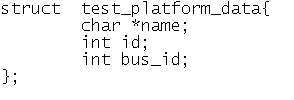
Here i have created pseudo device and driver to develop clear understanding of all these. In your board header file declare a private data structure according to resources used by your device. Here, i am declaring test_platfrom_data. The snippet 1 below will provide more information about members of test_platform_data.

Snippet 1

Snippet 1

In my board c file i have created instance of this structure  with appropriate data. This  user defined structure will passed to the driver w. Snippet 2 will provide you details about private data which is assigned to structure instance.

Snippet 2

Snippet 2

Now its time to define platform device in board file. In Linux kernel struct platform_device is declared. Lets create a instance of this structure. This will passed to kernel for registration of platform device. Snippet 3 will show you definition of platform device.

Snippet 3

Snippet 3

The main important point is the name of device.  Here in my case name of my device is “drivertest”.  From board init function add line(shown by snippet 4) to register this platform device.

After this edition in board file, compile kernel using appropriate cross compiler and boot your board with this kernel.

Snippet 4

Snippet 4

After success full booting of board, start making driver(.ko) file  for your registered device. Structure platfrom_driver is used to register platform driver. Here, snippet below shows the definition of platfrom_driver structure.  Register platform driver in init function using platfrom_driver_register.

Snippet 5

Snippet 5

Here, the impotent thing is the name of driver. Name of driver is as same as the name of device(in board file). On the registration of new platform driver, linux kernel compare its name with the previously defined all platform device name. If the match is found the probe function of the driver is called with  appropriate data which is responsible to initialize the device. The whole device structure is passed through probe function. The snippet below shows the subroutine for probe function.

Snippet 6

Snippet 6

In the probe function of driver,  i have extracted platform data from probe, which is assigned to the device at the booting time. This platform_data contains all the low level information about device. On the basis of this data, probe function initialize the device and irq using this data. Generally this data contains the information about module id, data rate, interrupt   etc..

I have compiled module and the output i is pasted below which shows the platform data is extracted from the probe.

Output

output sdfdfas

This is how the whole initialization of non dicoverable devices works.

24 Comments

Filed under Linux Device Driver, Platfrom device

Add new module to Linux kernel source code

Kernel modules are pieces of code that can be loaded and unloaded into the kernel upon demand. They extend the

functionality of the kernel without the need to reboot the system. If you want to add your code(module) to a Linux

kernel, the most basic way to do that is to add your source files to the kernel source tree, add entry of your module in

appropriate Makefile and Kconfig file  and recompile the kernel. In fact, the kernel configuration process consists

mainly of choosing which files to include in the kernel to be compiled. All the device drivers are written using these

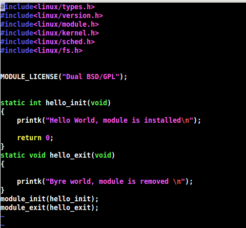
loadable modules.Let us add a very basic sample kernel module. Add this file to drivers/gpio directory in Linux kernel

source tree.

vim ./drivers/gpio/helloWorld.c helloWorld

helloWorld.c

helloWorld.c

Now we need to add configuration setting, so that we can add or remove this module from the By the time of Linux

kernel configuration(You can configure it from “make menuconfig”).  To do that add your modules entry in ./driver

/gpio/Kconfig file. Add below codes to ./drivers/gpio/Kconfig file.

vim ./drivers/gpio/Kconfig

vim ./drivers/gpio/Kconfig

Line 1 is the macro with using which our module can be configured.Line 3 states that this option can only be enabled if

CONFIG_ARM is enabled . Next We have to inform kernel to compile hello_world.c when HELLO_WORLD_MODULE

configuration is enabled.Add this to ./drivers/gpio/Makefile.

vim ./drivers/gpio/Makefile

vim ./drivers/gpio/Makefile

We have successfully added a new module to Linux kernel. Now lets test our new module with Linux kernel.To do that

first we need to give tool chain name to CROSS_COMPILE flag and architecture name to ARCH flag in Linux terminal.

Compilation process

Compilation process

Now configuration menu will appear. Navigate to Device Drivers—>GPIO Support —>Hello World Module  and enable

it. Now start compiling kernel and modules.

Your module will get inserted as a part of kernel.

Enjoy !!!

17 Comments

Filed under Uncategorized