In this post, i am going to explain step by step procedure to make simple driver which can blink led on Linux powered raspberry pi. Raspberry pi is a credit-card sized computer developed by Raspberry pi Foundation ,UK. The Raspberry pi is equipped by Brodcom BCM2835 SoC, which includes an ARM1176JZF-S core clocked with 700 MHz. Raspberry pi was originally shipped with 256 MB of RAM, later upgraded to 512 MB of RAM. This card sized computer uses the SD card for booting and data storing purpose.
This tutorial demonstrates how to develop and debug a basic hardware driver for Raspberry PI. It will demonstrate the following techniques:
- Controlling the BCM2708/BCM2835 peripherals by accessing their hardware registers
- Handling of interrupts in Device driver
- Creating a sysfs device object to provide user-mode control interface
Here, for my setup i am using raspberry pi model-A. I have compiled kernel(with my led blinking driver) for raspberry pi.
Compilation of Linux kernel for Raspberry pi
1. Get the kernel Source code for here.
2. Get the tools(cross-compiler) from here.
3. Extract both files in your home directory. Here, i have extracted in /home/bhargav/rpi/.
3. Set the environment variable CCPREFIX:
export CCPREFIX= /home/bhargav/rpi/tools-master/arm-bcm2708/arm-bcm2708-linux-gnueabi/bin/arm-bcm2708-linux-gnueabi-
4. Set the environment variable KERNEL_SRC:
export KERNEL_SRC=/home/bhargav/rpi/linux-rpi-3.2.27
5. In KERNEL_SRC: execute “make mrproper” to ensure you have a clean kernel source tree
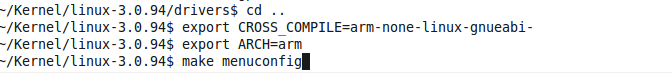
6. In KERNEL_SRC: execute below command to configure kernel source tree for raspberry pi
make ARCH=arm CROSS_COMPILE=${CCPREFIX} bcmrpi_defconfig
7. In KERNEL_SRC: execute below compile kernel source tree for raspberry pi
make ARCH=arm CROSS_COMPILE=${CCPREFIX}
This process will give you kernel Image file at < KERNEL_SRC>/arch/arm/boot/ which can be places as kernel.img in boot partition of MMC.
Adding LED blinking device in board file
To add led blinking driver support in your build, you have to register your device in the board file of your board.
Board file for raspberry pi is located at <KERNEL_SRC>/arch/arm/mach-bcm2708/bcm2708.c which includes the subroutines for registering of all devices.
First, you need to add your header file of driver in to <KERNEL_SRC>/include/linux/ directory.
Here i am adding blinkled.h in the same directory. The below image will provide you more details about contain of file.

Header file for led blink driver
Include this header file in board file for raspberry pi. Add the below code in board file.

Defining a device in board file
Here, i am declaring device named “LED_Blink” which has gpio number as a platform data on which it is connected.
Its time to register this declared device. In board file, bcm2708_init is a function which register all the peripherals devices with the kernel.
So, in this function we need to registered our device with the kernel platform bus. Add the below line in in bcm2708_init function which register our device(“LED_Blink”) with kernel.
This device is added as platform device. I am not going in to much details of platform device, explanation can be found here.

Registration of Device
At this stage we have registered our Led_Blink device to Linux kernel virtual bus. Now its time to write a driver for “Led_Blink” Device.
Writing driver for LED Blinking device
In the driver file, we need to declare one driver and register it with the kernel virtual bus with the same name which we gave to register device(“Led_Blink”). Linux kernel will compare the name of device and driver which is available on virtual bus and call the probe function of same driver. This is the basic concept of platform bus which is explained in the previous post.

Registration of Driver
Here, driver is declared with the probe and remove function. Important thing is the name of the driver which is same as the device which we declared in device( In board file). Init function is the first function, which will be called on the successfully insertion of driver in the kernel. In our init function we have registered the platform driver to the bus.
On availability of the same device on the bus, kernel will calls the probe function of the same driver. So, after init function, probe will get called by the Kernel subsystem. Basically, probe will do all the initialization of device(GPIO) .
According to the BCM2835 peripheral manual, the GPIO pins can be controlled by first configuring them as output by writing to one of GPFSELx registers and then writing to GPFSETx/GPFCLRx registers. We will define a structure describing the GPIO registers and provide functions for controlling GPIO pins using it.

Probe routine of LED blink driver
Above snippet shows the body of probe function. In the probe function, there are three impotent things are done.
1. Configure Pin as GPIO
The below snippet shoes the routines for set pin functionality and set output value of pin. This functions uses the structure pointer to access the registers of SoC.

Gpio Routines
2. Setup time for On and Off timing of LED
When timer elapse, state of pin will get changed and again timer will be re initialized from timer subroutine. The snipped below shows the body of time handler.
This subroutine causes the blinking of the LED.

Timer handler subroutine
3. Register /sys interface to change blink period from user domain
Sys interface is used to change the blinking period from user space. From the probe function BlinkLed_attr is registered for sys interface which has only one attribute name “period”. User can get and set time interval using this interface. s_BlinkPeriod variable is used to store blanking period. The snippet below shows the subroutines for same.

Sys interface routines
You can download full driver code from here.
You have to add this add this module to linux source code. Here are the steps to do that.
Now, its time to compile your tweaked kernel using the steps shows above. Repeat from steps #5.
Enjoy your driver !!!