Device driver to interface shift reg with Raspberry pi 2

Hello Folks, after a long time my schedule allowed me to write some thing.

Today i am going to explain you the way to interface the shift register  with Linux based raspberry pi 2 board.  The shift register is the sequential logic which can used for data storage/parallel to serial conversation/ parallel to serial conversation. Hardware based stack can be constructed using several shift resister.

Shift registers are broadly distinguished in two types.

  1. Serial in, parallel out (SIPO):  In this configuration data is serially inserted in to shift register and output will be in form of parallel data bits. This is register used when more output ports are needed then available. This allows several binary devices to be controlled using only three pins, the binary controlled devices are attached to the parallel outputs of the shift register, then the desired state of all those devices can be sent out of the microprocessor using a single serial connection.
  2. Parallel in, serial out(PISO):  In this configuration parallely inserted data to shift register and output will be serial stream of bits. This configuration used to add binary inputs and give it in single stream to process. In this less micro-controller  pins are required to read the data.

This tutorials demonstrate how to interface SIPO  shift register (sn74hc595) to the raspberry pi 2. In addition to this, it explains how to write Linux device driver to control this hardware.

The sn74hc595 has an 8 bit storage register and an 8 bit shift register. Data is written to the shift register serially, then latched onto the storage register. The storage register then controls 8 output lines. Lets examine the ping configuration of sn74hc595 first. That will give us understanding about “How to drive sn74hc595 ? “.
Top_view

Ping configuration of sn74hc595

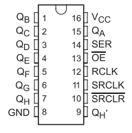
sn74hc595 register has 18 pins. which is shown in the image at left. Pin 16 is for VCC, which should be connected to 5v. Pin 8 is connected to common ground in the system. Pin number 1 to 7 and 15 is parallel data output pins.  Pin 14 is the serial data input pin.  Pin 11 is serial clock pin. when pin 11(SRCLK) goes from Low to High the value of pin 14(SER) is stored into the shift register and the existing values of the register are shifted to make room for the new bit. Pin 12 (RCLK) is used for latch. This pin should be low when data is written in the sift register. When it goes High the values of the shift register are latched to the storage register which are then outputted to pins Q0-Q7.  Pin 13 is to enable output. All latch output is enable if this pin is set to low.  Pin 10 is use for clear the output state on pins. Output pins will be cleared if low to high pulse is given to this pin. Default value of pin 10 is high.

How to co

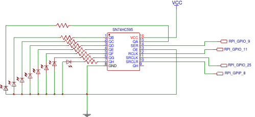
So to drive this register, we need to control 5 pins.  Pin # 14,13,12,11 and 10. We need to connect output pins to LEDs  to check output of shift register. Based on this, we have derived a circuit diagram.
First-schamatic

Circuit diagram

Above image shows circuit diagram. Here we are using GPIOs of raspberry pi to control shift registers. RPI GPIO 9 is used as serial data line when is connected to SER(pin 14) of sn74hc595 . RPI GPIO 11 is used as latch clock line which is connected to RCLK (pin 12) of sn74hc595. RPI GPIO 25 is used as serial clock line which is connected to SRCLK (pin 11) of sn74hc595.  RPI GPIO 8 is used as serial clear line which is connected to SRCLR(pin 10) of sn74hc595. In addition to this, it is essential to connect VCC ad 5v and Common Ground with RPI.

Now, its time to design driver to control these GPIO pins. Driver will expose sysfs interface to change value represented by leds. Value which is written to this sysfs file will be represented by leds which is connected with sn74hc595.

So, lets start understanding responsibilities of init function of driver. As part of initialization of this driver, we need to Configure pin 21, 22,23 and 24 as GPIO which corresponds to GPIO 8, 9, 25 and 11.  In addition to this, we have to resigter sysfs class and device to control shift register.

Les take a deep dive  into source code of driver.  As first part we have declared to global GPIOs pins which can be used in all driver code. As per our circuit design above we have declared the pins which is shown in below code snippet.

declatation of GPIO

GPIO Declaration

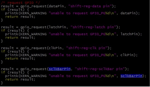
As part of initialization we have to configured this pins as GPIO pins. Below code snippet configures and request this pings as GPIO. The below snippet is part of init function of driver.
requrst_GPIO

Configure Pings as GPIO

Now we have to configure this pins as output pins and set to appropriate default value.  As explained above we need to configure Pin 10(serial clock bar) to high.  The default value of all other pins will be low. The below snippet shows this.

op

Configure GPIOs as output

Lets register sysfs interface to control output of shift register.  I have created new sysfs class and device to represent shift resister.

sysfs

Registration of Sysfs interface

Every device interface in sysfs has attributes which can be read or write. Corresponding read write function registered with the attribute will get called when read or write operation performed on the this interface. Below snippet shows the registration of attribute named value with set and get value callback.

The attribute name should be the same as given by the time of creating file. Here we have given name as dev_attr_value. So out attribute is the value for which we have registered set and get routine. when we tried to read the file(sysfs Interface) from application, get_value_callback will be triggeres in the driver. In case we tried to write some value to file(sysfs Interface) from application,  set_value_callback will be triggers with the value to write in shift register.

attribute

Registration of sysfs device attribute

On low to high transmission of clock pulse,  internal register(storage register) value will shift by one and value on data pin will be moved to LSB of internal register. At the end after 8 bit data is shifted to the shift register,  by providing the latch pulse from low to high, all data from the internal register(storage Register) is latched to shift register pins. We have connected LEDs to the output pins of shift register.  This is shown by below snippet. To write some value to shift register,  it is essentials to put that value on data pin of shift register and then provide a clock pulse. On this clock pulse, data on internal register gets shifted and adds new bit(which is present on data pin) at the end presently shifted data.  So here in code, I am setting bit by bit this new_value variable on data pin and after setting one bit providing clock pulse. At the end i am providing the latch pulse so the 8 bit value which stored in the internal storage register will be  latched to the pins.
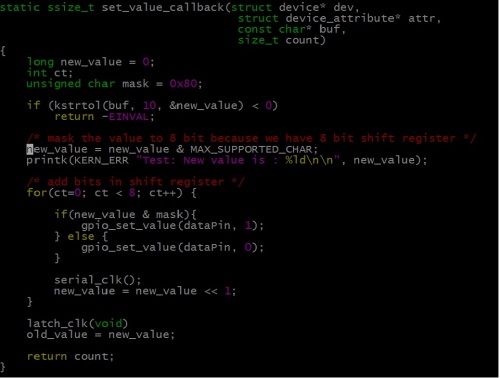
set_attribute

Routine to set value

When user application tries to  read the value from the sysfs interface, the get_value_callback will get called.  The callback will return old_value which was updated by the get value callback. The below snippet shows that. get_attribute

Here you can get full code for this driver. you can follow this steps to add module to Linux kernel source code and compile it.

Cheers !!!

Leave a comment

Filed under Linux Device Driver, Uncategorized

Fundamentals of PCI device and PCI drivers.

Hello Folks, today i am going to talk about the PCI subsystem and Process of developing PCI based Device driver.

PCI is a local bus standards, which used to attach the peripheral hardware devices with the Computer system. So it defines how different peripherals of a computer should interact. A parallel bus which follows PCI standards is knows as PCI bus. PCI stands for Peripheral Component Interconnect.

The devices which are connected to PCI bus are assigned address in the processor’s address space. This memory(addresses in processor’s address space) contains control, data and status registers for the PCI based  device, which is shared between CPU and PCI based device. This memory will be controlled by the device driver/kernel to control the particular device connected over PCI bus and share information with it. PCI device became  like a memory mapped device.

The PCI address domain contains the three different type of memory which has to be mapped in the processor’s address space.

1. PCI Configuration Address space

Every PCI based  device has a configuration data structure that is in the PCI configuration address space. The length of configuration data structure is 256 bytes. This data structure used by system/kernel to identify the type of device. The location of this data structure is depend upon the slot number where the device is connected on the board. eg. Device on slot 0 has its configuration data structure on 0x00 but if you connect same device on slot 1 its configuration data structure goes to 0xff. You can get more details about layout of this configuration data structure here.

At power on, the device has no memory and no I/O ports mapped in the computer’s address space. The firmware initializes PCI hardware at system boot by mapping each region to a different address. By accessing PCI controller register, the addresses to which these regions are currently mapped can be read/write from the configuration space, By the time a device driver accesses the device, its memory and I/O regions have already been mapped into the processor’s address space.

So To access configuration space, the CPU must write and read registers in the PCI controller. Linux provides the standard API to to read/write the configuration space. The exact implementation of this API is vendor dependent.

int pci_read_config_byte(struct pci_dev *dev, int where, u8 *val);

int pci_read_config_word(struct pci_dev *dev, int where, u16 *val);

int pci_read_config_dword(struct pci_dev *dev, int where, u32 *val);

The above APIs are used to read the different size of data configuration space. The first argument is the pci device node, the second argument is the byte offset from the beginning of configuration space and third argument is the buffer to store the value.

int pci_write_config_byte(struct pci_dev *dev, int where, u8 val);

int pci_write_config_word(struct pci_dev *dev, int where, u16 val);

int pci_write_config_dword(struct pci_dev *dev, int where, u32 val);

The above APIs are used to wirte the different size of data configuration space. The first argument is the pci device node, the second argument is the byte offset from the beginning of configuration space and third argument is a value to write.

2. PCI I/O address space 

This is 32 bit memory space which can be access by using CPU IO access instructions. PCI devices place their registers for control and status in PCI I/O space.

3. PCI memory Address space

This is 32 bit or 64 bit memory space which can be  access as the normal memory locations. The base address of the this memory space is stored in the BAR register. The PCI memory space have higher performance than access to PCI I/O space.

Specification of I/O and memory address is device depended. I/O and memory address can be access by normal memory read write operations.

We have gone through the basic memories region of PCI device. Now its time to understand the different initialization phase of the of PCI devices.

Linux kernel devices the PCI initialization in to three phase.

1. PCI BIOS :  It is responsible for performing all common PCI bus related task. Enable the access to PCI controlled memory. In some CUP architecture it allocate the interrupts for PCI bus.

2. PCI Fixup : It maps the configuration space, I/O space and Memory space to the RAM. Amount of memory for I/O region and memory region can be identified from the BAR registers in configuration space. In some of CPU architecture Interrupts are allocated at this stage. It also scan all the bus and find out the all present devices in the system and create pci_dev structure for each present device on the bus.

3. PCI Device Driver :  The device driver registers the driver with product Id and vendor Id. The PCI  subsystem checks for the same vendor Id and product id in its list of devices registered at the Fixup phase. if it gets the device with same product Id and vendor Id the it initialize the device by calling the probe function of driver which registers further device services.

So, this was just an overview of the how PCI based devices works with the Linux kernel.

Stay tunes !!

7 Comments

Filed under Linux Device Driver

Synchronization mechanisms inside Linux kernel

Hello folks, today i am going to talk about the synchronization mechanism which is available in Linux kernel. This post may help you to choose right synchronization mechanism for uni-processor or SMP system. Choosing wrong mechanism can cause crash to kernel or it can damage any hardware component.

Before we begin, lets closely examine three terminology which will use frequently in this post.

1. Critical RegionA critical section  is a piece of code which should be executed under mutual exclusion. Suppose that, two threads are updating the same variable which is in parent process’s address space. So the code area where both thread access/update the shared variable/resource is called as a Critical Region. It is essential to protect critical region to avoid collusion in code/system.

2. Race Condition: So developer has to protect Critical Region such that, at one time instance there is only one thread/process which is  passing under that region( accessing shared resources). If  Critical Region  doesn’t protected with the proper mechanism, then there are chances of Race Condition.

Finally, a race condition is a flaw that occurs when the timing or ordering of events affects a program’s correctness. by using appropriate synchronization mechanism or properly protecting Critical Region  we can avoid/reduce the chance of this flaw.

3. Deadlock: This is the other flaw which can be generated by NOT using proper synchronization mechanism. It is a situation in which two thread/process sharing the same resource are effectively preventing each other from accessing the resource, resulting in both programs ceasing to function.

So the question comes to mind is “what is synchronization mechanism ?” Synchronization mechanism is set of APIs & objects which can be use to protect critical region and avoid deadlock/race condition.

Linux kernel provide couple of synchronization mechanism.

1. Atomic operation: This is the very simple approach to avoid race condition or deadlock.  Atomic operators are operations, like add and subtract, which perform in one clock cycle (uninterruptible operation). The atomic integer methods operate on a special data type, atomic_t. A common use of the atomic integer operations is to implement counters which is updated by multiple threads. The kernel provides two sets of interfaces for atomic operations, one that operates on integers and another that operates on individual bits. All atomic functions are inline functions.

1. APIs for operations on integers:

atomic_t i                 /* defining atomic variable i */

atomic_set(&i, 10);      /* atomically assign value(here 10) to atomic variable i */

atomic_inc(&i);           /* atomically increment value of i variable (i++ atomically), so i = 11 */

atomic_dec(&i);          /* atomically decrement value of i variable (i– atomically), so i = 10 */

atomic_add(4, &i)   /* atomically add 4 with value of i (i = 10+4) */

atomic_read(&i);       /* atomically read and return  value of i (14) */

2. APIs for operates on individual bits:

Bit-wise APIs operate on any generic memory addresses. So there is no need to for explicitly defining an object with the type of atomic_t.

unsigned int i = 0;     /* defining a normal variable (i = 0X00000000)*/

set_bit( 5, &i );    /*atomically  Set 5th bit of the variable i  ( i = 0X00000010)*/

clear_bit( 5, &i );  /* atomically clear 5th bit of the variable i  ( i = 0X00000000)*/

2. Semaphore: This is another kind of synchronization mechanism which will be provided by the Linux kernel. When some process is trying to access semaphore which is not available, semaphore puts process on wait queue(FIFO) and puts task on sleep.  That’s why semaphore is known as a sleeping lock. After this processor is free to jump to other task which is not requiring this semaphore. As soon as semaphore get available, one of task from wait queue in invoked.

There two flavors  of semaphore is present.

  • Basic semaphore
  • Reader-Writter Semaphore

When a multiple threads/process wants to share data, in the case where read operation on data is more frequent and write operation is rare. In this scenario Reader-Writter Semaphore is used.  Multiple thread can read a data by same time. The data will be only locked(all other read thread should wait) when one thread write/update data. On the other side writers has to wait until all the readers release the read lock. When writer process release lock the reader from wait-queue(FIFO) will get invoked.

Couple of observations about nature of semaphore :

  1.  Semaphore puts a task on sleep.  So the semaphore can be only used in process context. Interrupt context can not sleep.
  2.  Operation to put task on sleep is time consuming(overhead) for CPU. So semaphore is suitable for lock which is holding for long term. Sleeping and invoking task over kills CPU if semaphore is locked and unlocked for short time via multiple tasks.
  3.  A code holding a semaphore can be preempted. It does not disable kernel preemption.
  4.  After disabling interrupts from some task, semaphore should not acquired.  Because task would sleep   if it fails to acquire the semaphore, at this time the interrupt has been disabled and current task cannot  be scheduled out.
  5.  Semaphore wait list is FIFO in nature. So the task which tried to acquire semaphore first will be waken up from wait list first.
  6.  Semaphore can be acquired/release from any process/thread.

3. Spin-lock: This is special type of synchronization mechanism which is preferable to use in multi-processor(SMP) system. Basically its a busy-wait locking mechanism until the lock is available. In case of unavailability of lock, it keeps thread in light loop and keep checking the availability of lock. Spin-lock is not recommended to use in single processor system.          If some procesq_1 has acquired  a lock and other process_2 is trying to acquire lock, in this case process 2 will spins around and keep processor core busy  until it acquires lock. process_2 will create a deadlock, it dosent allow any other process to execute because CPU core is busy in light loop by semaphore.

Couple of observations about nature of spinlocks:

  1. Spinlocks are very much suitable to use in interrupt(atomic) context becaue it dosent put process/thread in sleep.
  2.  In the uni processor environment, if the kernel acquires a spin lock, it would disable preemption first ; if the kernel releases the spin lock, it would enable preemption. This is to avoid dead lock on uni processor system. EG: In uni processor system, thread_1 has acquired spinlock. After that kernel preemption takes place, which puts thread_1 to the stack and thread_2 comes on CPU. Thread_2 tries to acquire same spin-lock but which is not available. In this scenario, therad_2 will keep CPU busy in light loop. This situation dose not allow other thread to execute on CPU. This create deadlock.
  3. Spin-locks is not recursive
  4.  Special care must be taken in case where spin-lock is shared b/w interrupt handler and thread. Local interrupts must be disabled on the same CPU(core) before acquiring spin-lock. In the case where interrupt occurs on a different processor, and it spins on the same lock, does not cause deadlock because the processor who acquire lock will be able to release the lock using the other core. EG: Suppose that an interrupt handler to interrupt kernel code while the lock is acquired by thread. The interrupt handler spins, wait for the lock to become available. The locker thread, does not run until the interrupt handler completes.  This can cause dead lock.
  5. When data is shared between two tasklet, there is not need to disable interrupts because tasklet dose not allow another running tasklet on the same processor. Here you can get more details about nature of tasklets.

There two flavors  of spin-lock is present.

  • Basic spin-lock
  • Reader-Writter Spin-lock

With increasing the level of concurrency in Linux kernel read-write variant of spin-lock is introduces. This lock is used in the scenario where many readers and few writers are present. Read-write spin-lock can have multiple readers at a time but only one writer and there can be no readers while there is a writer. Any reader will not get lock until writer finishes it.

4. Sequence Lock: This is very useful synchronization mechanism to provide a lightweight and scalable lock for the scenario where many readers and a few writers are present. Sequence lock maintains a  counter for sequence. When the shared data is written, a lock is obtained and a sequence counter is incremented by 1. Write operation makes the sequence counter value to odd and releasing it makes even. In case of reading, sequence counter is read before and after reading the data. If the values are the same which indicates that  a write did not begin in the middle of the read. In addition to that, if the values are even, a write operation is not going on. Sequence lock gives the high priority to writers compared to readers. An acquisition of the write lock always succeeds if there are no other writers present. Pending writers continually cause the read loop to repeat, until there are no longer any writers holding the lock. So reader may sometimes be forced to read the same data several times until it gets a valid copy(writer releases lock). On the other side writer never waits until and unless another writer is active.

So, every synchronization mechanism has its own pros and cons. Kernel developer has to smartly choose appropriate synchronization mechanism based on pros and cons.  

Stay tuned !!!!

10 Comments

Filed under Synchronization in linux kernel

Concept of Shared IRQs in linux

In this post, i am gonna talk about the shared IRQ and how Linux kernel handle shared IRQs.

As wikipedia states “In a computer, an interrupt request (or IRQ) is a hardware signal sent to the processor that temporarily stops a running program and allows a special program, an interrupt handler, to run instead”.

In any embedded system, When a device needs the CPU it sends a request to the CPU. When the CPU gets this request it stops everything what it is doing (and save in memory where the CPU left for the task it was doing) and then it serve the device that sent the request. After serving the device, it gets the work what it was doing from cache/HDD and carry on what it was doing before that interrupt was sent. This request is known as IRQ (interrupt request). So, interrupts are interruptions of a program caused by hardware, when it needs an attention from CPU.

There are limited Interrupts lines(pins) are available on every SoC. Idealistically, one IRQ line can only serve one device. It menace that number of device that can communicate with the processor is equal to the number of IRQ lines available on processor. Which is not enough as per the modern embedded device complexity. As a solution of this situation, modern hardware,  has been designed to allow the sharing of interrupt line among couple of device. Its a responsibility of a software developer to enable/disable appropriate hardware for interrupt on shared line and maintain the list of IRQs for shared line. On the arrival of interrupt on shared line, appropriate ISR from list should gets called to server the device.

Here as a part of this post we will going to explore how shared IRQ can registered and used with Linux kernel.

request _irq() is the function, which is used to request and register normal IRQ with Linux kernel. The same function is used to registered shared IRQ. The difference is SA_SHIRQ bit must be specified in the flags argument when requesting shared interrupt. On the registration of shared IRQ kernel checks for any other  handler exists for that interrupt and  all of those previously registered also requested interrupt sharing. If it found any other handler for same IRQ number, it then checks dev_id parameter is unique, so that the kernel can differentiate the multiple handlers. So it is very essential that dev_id argument must be unique. The kernel keeps a list of shared handlers associated with the interrupt, and dev_id is used as the signature that differentiates between all handlers. If two drivers were to register same dev_id  as their signature on the same interrupt, things might get mixed up at interrupt occurrence , causing the kernel to oops when an interrupt arrived. When a hardware device raises the interrupts on IRQ line, the kernel invokes every handler registered for that interrupt, passing dev_id, which was used to register the handler via request_irq().

When interrupts occurs on shared IRQ line, kernel invokes each and every interrupt handler registered with it by passing each its own dev_id. Shared IRQ handler should quickly check the dev_id with its own to recognize its interrupts and it should quickly return with return value of IRQ_NONE if own device has not interrupted(dev_id does not match). If dev_id matches ISR should return IRQ_HANDLE so kernel stops calling nest interrupt handler. In addition to this, driver using shared IRQs should not enable or diable IRQ. If it does, things might go wrong for other devices sharing the line; disabling another device’s interrupts for even a short time may create latencies that are problematic for that device.

Be very cautious while playing with shared interrupts !!

cheers 🙂

6 Comments

Filed under interrupts in linux, Shared IRQ

The story of device tree for platfrom device….

The whole story starts from non discover-able devices in the system. This post will provide you information about non discoverable devices as well it will provide you one of way of Linux kernel to deal with it. The second and fresh way is device tree.

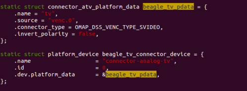
Kernel starts, it has to initialize the drivers for the devices on the board. But often on embedded systems, devices can’t be discover at running time(i2c, spi, etc.). In this case, the Linux kernel has a c (board file) file that initialize these devices for the board. The below image shows structure for non discoverable devices and platform data for same. This will be registered with the virtual bus named platform bus and driver will also register it self with platform bus with the same name.

In this method,  kernel must be modified/compiled for each board or change in hardware on board.  Kernels are typically built around a single board file and cannot boot on any other type of system. Solution of this situation is provided by “Device tree”. A device tree is a tree data structure with nodes that describe the physical devices on the board. While using device tree, kernel no longer contains the description of the hardware, it is located in a separate binary blob called the device tree blob. The device tree is passed to the kernel at boot time. Kernel reads through it to learn about what kind of system it is. So on the change of board only developer needs to change device tree blob and that it new port of kernel is ready.

Platfrom device

Platform device

Here, you will get a good article on device tree format. It is recommended to go through it first at this stage.

Platform devices can work with dtb enabled system with out any extra modification. If the device tree includes a platform device that device will be instantiated and matched against a driver. All resource data will be available to the driver probe() in a usual way. The driver dose now know wither this device is not initialized with hard-cored. in board file.

Every device in the system is represented by a device tree node. The next step is to populate the tree with a node for each of the devices. The snippet below shows the dtb with node name “ps7-xadc”.  Every node in the tree represents a device, which must have a compatible property. compatible is the key using which an operating system uses to decide which device driver to bind to a device. In short compatible(ps7-xadc-1.00-a) specifies the name of the platform device which will get registered with bus.

Platform device in DTB

Platform device in DTB

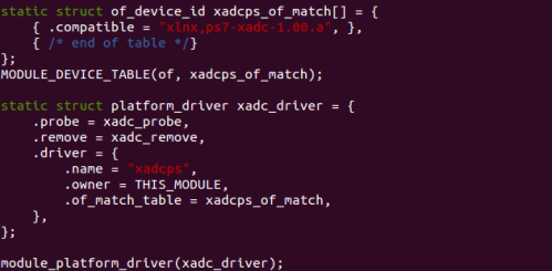
On other side, in device driver when platform deriver structure is declared, it stores a pointer to “of_device_id”. This is shown by the below snippet. This name should be same which was given in the dtb file.  Now, when driver with name of “ps7-xadc-1.00.a” will get register with the platform bus, probe of that driver will get called.

Platform driver registration

Platform driver registration

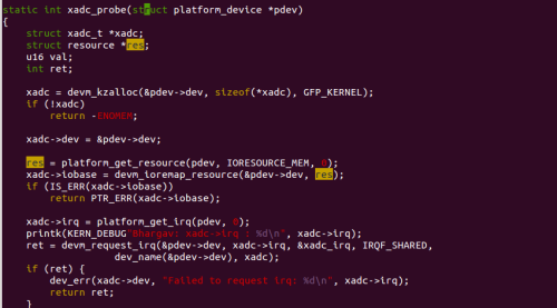
The below snippet shows the probe function of the driver. In the probe, function platform_get_resource() provides property described by “reg” in dtb file. In our case base address of register set(0xf8007100) for hardware module and offset from the base address(0x20)  can be retrieved. Using which driver can request the memory region form the kernel. As same, function platform_get_irq() provides the property which id describe by “interrupts” in dtb file.

Getting device specific data

Getting device specific data

After garbing all details from dtb file, probe will register device as a normal way.  This is very straight forward procedure using which platform drivers work with device trees. As a result of this,  no need to declare platform_device in board file.

Cheers !!!

4 Comments

Filed under Device tree, Linux Device Driver, Platfrom device, Uncategorized

Add new system call to linux kernel…

This post gives you a deep understanding about system call and a way to add a new system call to Linux kernel.

System call is call to kernel service made using software interrupts. An interrupt is a way to notify kernel about occurrence of some event, and this results in changes in the sequence of instructions that is executed by the CPU. A software interrupt, also referred to as an exception, is an interrupt that originates by software in user mode.  User mode is one of two distinct execution modes of operation for the CPU in Linux. It is a non-privileged mode in which each process starts out. So these processes dose not have privilege to access memory allocated by the kernel.

The kernel is a program that constitutes the core of an operating system, and it has complete control over all resources on the system and everything that occurs on it. When a user mode process wants to use a service provided by the kernel (i.e., access system resources other than the limited memory space that is allocated to the user program), it must switch temporarily into kernel mode, also called system mode, by means of a system call.

Kernel mode has all privileges, including root access permissions. This allows the operating system to perform restricted actions such as accessing hardware devices or the memory management unit. System calls can also be viewed as gateway to kernel through which programs request services from the kernel.

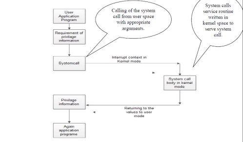
Flow Graph of System call

Flow Graph of System call

Above Figure shows the general flow graph of the system call. User application lies in user space and system call body is in kernel space. In the user application the kernel privilege data can accessed by the system call. System call body will start a new kernel thread to serve the user application.

I would like to take you through a sequence of steps in creating your own system call.

1. Editing kernel source code to add system call

2. Compiling modified kernel for x86 machine

3. Building an application to text your system call

Add System Call

Lets install all the dependency packages (libncurses5-dev)

sudo apt-get install libncurses5-dev

Then update and install all the upgrade your machine.

sudo apt-get update && sudo apt-get upgrade

Download kernel source code. Here, i am using the kernel 3.2, there are various other versions are available here. Below command also downloads kernel.

wget http://www.kernel.org/pub/linux/kernel/v3.0/linux-3.X.tar.bz2

Extract the tarball to ~/linux-3.x/

sudo tar -xvf linux-3.X.tar.bz2 -C ~/linux-3.x/

Change the directory to ~/linux-3.x/

cd ~/linux-3.x/

Now lets add the system call in the above downloaded kernel.

First, we need to create a new directory in the root of the kernel sources tree. Name of new directory is “new_syscall”. In this directory, we need to create two files.

1. Implementation of our system call itself, hello.c:

The below snippet is the body of system call. Basically, This function is the one which should  called in the kernel space when appropriate system call is invoked from the user space.

Implimentation of syscall

Implementation of system call

2. Makefile to build it

After creating the system call, we need to set up the Makefile to build it. Following snippet will show you the contain of Makefile which is used to build our system call.

Makefile for hello.c

Makefile for hello.c

This is a very simple Makefile, because the build system of the kernel takes care of most of the work. This concludes the new files that will need to be added to the kernel sources to make a new system call.

There are a few source files in the kernel that will need to be updated in order to add the new system call to be added to the kernel build system. The first, and simplest of these is the root-level Makefile. Find the following line, around line 711 of the root-level Makefile:

core-y := kernel/ mm/ fs/ ipc/ security/ crypto/ block

Add your newly created directory “new_syscall” as shown :

core-y := kernel/ mm/ fs/ ipc/ security/ crypto/ block/ new_syscall/

Now, open the include/linux/syscalls.h file, and add a definition for your new system call.

asmlinkage long sys_hello(void);

This step expose your system call  to other parts of the kernel. While this is not necessary for this simple system call, it is still good practice for when adding a real system call to the kernel.

NOTE: asmlinkage keyword tells your compiler to look on the CPU stack for the function parameters, instead of registers. System calls are services that userspace can call to request the kernel to perform something for them. These functions can not behave like normal functions, where parameters are typically passed by writing to the program stack, but instead they are written to registers. While still in userspace, calling a syscall requires writing certain values to certain registers. The system call number will always be written in eax, while the the rest of the parameters will go into other registers.

At this stage, you simply need to add the name of your system call to arch/x86/include/asm/unistd_32.h. Register the system call symbolic name with the kernel by adding system call number and system call name as below.

#define __NR_setns 346

#define __NR_sys_hello 347 <Add this line >

#ifdef __KERNEL__

#define NR_syscalls 348 <add 1 in total number of system call>

#define

The kernel maintains a list of all registered system calls in the system call table. This table assigns each valid system call a unique system call number which cannot be changed or recycled(which is given in above step). Processes do not refer to system calls by name, but rather by their system call number.

The final file that needs to be updated is the system call table, which resides in arch/x86/kernel/syscall_table_32.S. Add the definition for your new system call, by adding the following:

.long sys_hello

After configuring the systemcall perfectly kernel compilation is done to use system call from user domain.

Compiling modified kernel

Linux kernel can be compiled natively in the Linux environment using the native “gcc” compiler. Make files allow configuration changes using particular make options. The steps involved in compiling the kernel are:

1. Call the make utility within the un-tarred Linux kernel code (in this case Linux-3.2) directory with the required option – menuconfig, defconfig, xconfig, oldconfig and so on. menuconfig is used to edit the text based version of linux. xconfig is used to edit the windows and other GUI tools in KDE system and gconfig is used to edit same but in gnome system. I have used “make oldconfig”, which can configure new kernel as my existing kernel configuration. Before this the directories can be cleaned using the “make mrproper” and “make clean” command.

2. Once the compilation configuration is done use the “make” command to compile the kernel. To compile project, first need to compile each source file into an object file, this in turn needs to be linked with system libraries into the final executable file. This all is done by build system of Linux kernel.

3.  Once the kernel compiles successfully use the make modules and then the make modules_install options to compile and install modules into the kernel. Loadable modules are compiled and installed in the /lib/modules directory

4.  Then use the “make install” command to install the kernel in the /boot partition.

5.  Then switch to the /boot partition and use the “mkinitramfs” command with the –o option to create the RAM disk file as shown mkinitramfs –o initrd.img-<kernel_version_number>. You can get kernel version number by simple typing “uname -a” command on your terminal.

6.  GRUB (GRand Unified Bootloader) is a boot loader package developed to support multiple operating systems/kernel and allow the user to select among them during boot-up. After installing the modules and kernel it is essential to update the grub file to see the installed kernel version in the boot option. So, use “update-grub” command to update the boot entries in the grub file.

Thats it. You have installed new kernel in your system. Now just reboot your system and and select newly compiled kernel from grub selection menu.

Building an application

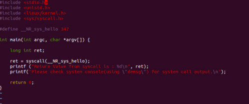
That’s it ! you have successfully added new system call to the kernel.  For simple testing of the system application program is essential which can call system call. Below application is test application for your system call. This application will invoke __NR_sys_hello from the kernel space using syscall().

Test app for developed system call

Test application for developed system

Compile the program, run it and check the dmesg command to see the “Hello World ! I am your system call.” output. Use below commands to check the output of your system call.

$ gcc hello.c -o hello
$ ./hello 
$ Return Value from syscall is : 0
$ Please check system console(using "dmesg") for system call output. 
 
$ dmesg

Cheers… you have done it !

Leave a comment

Filed under Linux Device Driver

Concept of ISR in Linux

In this article, i am going to discuss about Interrupt handling mechanism of Linux kernel.

So the story starts from When an interrupts occurs, the processor looks if interrupts are masked. If they are, nothing happens until they are unmasked. When interrupts become unmasked, if there are any pending interrupts, the processor picks one. Then the processor executes the interrupt by branching to a particular address in memory. The code at that address is called the interrupt handler. When the processor branches there, it masks interrupts (so the interrupt handler has exclusive control) and saves the contents of some registers in stack. When the handler finishes executing, it executes a special return-from-interrupt instruction that restores the saved registers and unmasks interrupts.

The problem over here is :

The Corresponding interrupt is disabled during the execution of a interrupt handler, the interrupt handler expected to be finish fast But, what if you have to do a lot of data processing, memory allocation in a interrupt handler.

After kernel release of 2.6 this problem is resolved by designing and developing proper interrupt handling mechanism. Which splits he interrupt handling in to two parts. 

  1. Top-Half: The top half is the real interrupt handler: It just tells the kernel to run the bottom half, and exits. The kernel guarantees that the top half is never re-entered: if another interrupt arrives, it is queued until the top half is finished. Because the top half disables interrupts, it has to be very fast.
  2. Bottom-Half: The bottom half is run after the interrupts are processed(Top half is executed).The interrupts are not disabled while the bottom half is run, so it can do slower actions.

NOTE: Its totally device driver developers choice to split interrupt processing or not. If the ISR is going to very short and can be managed then there is no need of  bottom-half. Similarly, if the disabled interrupt for a long time is OK for use case, then healthy top half is also possible. So, it is a totally design decision.

Linux provides three mechanism to implement bottom half.

1. softIrq : 

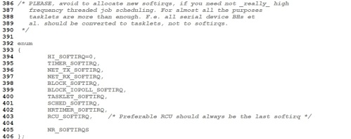
It is a vector of 10 different entries (in kernel 3.16) supporting variety of bottom half processing also called software interrupt. All entries are shown by the image below.

Linux/include/linux/interrupt.h

Linux/include/linux/interrupt.h

  • Softirqs are statically allocated at compile-time. So there are fixed number of softirq and they run in priority order.
  • Softirqs have strong CPU affinity, so they are reserved for most of time critical and important bottom half processing on the system.
  • softirq is guaranteed to run on the CPU it was scheduled on in SMP systems.
  • It Runs in interrupt context, so Interrupt context cannot perform certain actions that can result in the kernel putting the current context to sleep, such as downing a semaphore, copying to or from user-space memory or non-atomically allocating memory
  • it can’t preempted and can’t scheduled
  • Atomic execution
  • it can run simultaneously on one or more processor, even two of the same type of softirq can run concurrently

Softirqs are most often raised from within interrupt handlers. First the interrupt handler(top half) performs the basic hardware-related work, raises the softirq, and then exits. After the kernel is done processing interrupts, it checks wither any of the softirqs have been raised or not. Code flow in Linux kernel for interrupt handling is explained below.

Interrupt

 | do_IRQ()  (top half which masks all interrupts and invoke softirq)

   | irq_exit() (Release all masked interrupts)

     | invoke_softirq() (Kernel checks for the any pending invoked irq)

       | do_softirq() (Execution of softirq (bottom half) with )

2. Tasklet

Tasklets are build on top of softirq. The central idea of tasklet is to provide rich bottom half mechanisum. Only below points diffres from softirq.

  • Tasklets have a weaker CPU affinity than softirqs
  • Unlike softirqs, tasklets are dynamically allocated.
  • A tasklet can run on only one CPU at a time.
  • Runs in interrupt contex, Interrupt context cannot perform certain actions that can result in the kernel putting the current context to sleep, such as downing a semaphore, copying to or from user-space memory or non-atomically allocating memory
  • Atomic execution
  • Two different tasklets can run concurrently on different processors, but two of the same type of tasklet cannot run simultaneously on same processor.
  • Tasklet is strictly serialized wrt itself, but not wrt another tasklets.
  • Tasklet runs on same CPU from where is raised

Why softIRQ if tasklet is there ?

I’ll explain the need of softirq. That’s the networking code. Say you get a network packet. But to process that packet, it takes a lot of work. If you do that in the interrupt handler, no other interrupts can happen on that IRQ line. That would cause a large latency to incoming interrupts and perhaps you’ll overflow the buffers and drop packets. So the interrupt handler only moves the data off to a network receive queue, and returns. But this packet still needs to be processed right away. Before anything else. So it goes off to a softirq for processing.But Now you still allow for interrupts to come in. Perhaps the network interrupt comes in again on another CPU. The other CPU can start processing that packet with a softirq on that CPU, even before the first packet was done processing. the same tasklet can’t run on two different CPUs, so it doesn’t have this advantage. In fact if a tasklet is scheduled to run on another CPU but is waiting for other tasklets to finish, and you try to schedule the tasklet on a CPU that’s not currently processing tasklets, it will notice that the tasklet is already scheduled to run and not do anything. So tasklets are not so reliable when it comes to latencies.

3. Workqueue

Workqueues are also like tasklets. They are useful to schedule a task that for future. There is some identical difference between  two,

Runs in kenrel process context. Because work queues run in process context (kernel threads), they are capable of sleeping

  • Non atomic execution.
  • Workqueue runs on same CPU from where is raised
  • Higher latency compared to tasklet.

NOTE: This article contains only conceptual details of Interrupt handling mechanism of Linux. 

8 Comments

Filed under interrupts in linux

Virtualize(Emulate) your raspberry pi on windows…

Today, I am gonna talk about emulation of raspberry pi on windows.

This post is for specifically windows lovers 🙂

What is emulator ?

As wiki states, An emulator is hardware or software or both that duplicates (or emulates) the functions of one computer system (the guest) in another computer system (the host), different from the first one, so that the emulated behavior closely resembles the behavior of the real system (the guest).

It means that, virtual raspberry pi environment will be set up. Using which we can develop and test any application when Raspberry pi is not to hand, or when it’s not convenient or possible to power it up.

Here, in this post i am explaining to do this in four easy steps.

1. Get ARM emulator for windows

Raspberry pi has a ARM 11 based SoC. Open source processor emulator QEMU has a support for ARM architecture.  The QEMU site itself does not have a Windows binary download. Some one(Eric Lassauge) has tweaked qemu for windows. You can get latest qemu from here.

Extract the ZIP file to a folder on your PC.

2. Get kernel for raspberry pi with Qemu support

Here, are the steps to compile Linux kernel with qemu support.

To escape this step toy can just download the pre-compiled image from here.

Move this file to the QEMU folder which is created in previous step.

3. Get any of Raspi distro image

I am using the raspian “raspbmc” image. You can download this image from raspberry pi site.

Extract the file and put it in qemu folder.

4. Finally launching the emulator

Now, its time to launch the emulator with your kernel and disc image. The below command has to be hit on dos prompt on windows.

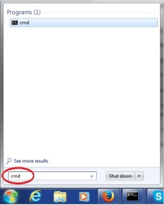
To do that, press Window button, search cmd in search bar. You will get one application named “cmd”. Open that application to write command. This is basically Dos prompt. The below image will provide you more information about it.

Finding cmd prompt in windows 7

Finding cmd prompt in windows 7

So, navigate to the directory where you have extracted qemu and all downloaded binaries.

Hit the below command to start qemu-arm for raspberry pi. In my case, i have kernel-qemu (which is downloaded in step #2) is the kernel for raspberry pi and raspbmc.img (which is downloaded in step #3)  is the image of file system.

qemu-system-armw.exe -M versatilepb -m 256 -cpu arm1176 -no-reboot -serial stdio -kernel kernel-qemu -hda raspbmc.img -append “root=/dev/sda2 panic=1”

The break down of the above command is :

1)  qemu-system-armw : the command to emulate an arm system on windows

2) -M versatilepb : the machine we need to emulate

3)  -m 256 : the amount of memory set that this version of the R-Pi has (The maximum memory size you can specify is 256Mb – that’s a limitation of QEMU for this hardware emulation – it may not work if you specify more)

4) -cpu arm1176 : the cpu we need to emulate

5) -no-reboot -append “root=/dev/sda2 panic1” : we mount our root filesystem to /dev/sda in the emulated R-Pi

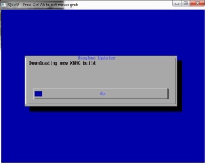
installation of raspBMC

installation of raspBMC

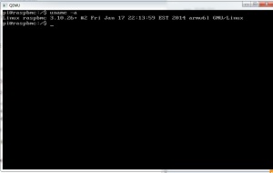
First time,qemu will run raspbmc setup  and configure it accordingly. After setup, u will get command prompt of raspbmc.

rpi shall

rpi shall

And thats it !!!

you are done with your virtual raspi configuration.

6 Comments

Filed under Uncategorized

Make Own LED blinking Driver for Raspberry pi ….

In this post, i am going to explain step by step procedure to make simple driver which can blink led on Linux powered raspberry pi. Raspberry pi is a credit-card sized computer developed by Raspberry pi Foundation ,UK. The Raspberry pi is equipped by Brodcom BCM2835 SoC, which includes an ARM1176JZF-S core clocked with 700 MHz. Raspberry pi was originally shipped with 256 MB of RAM, later upgraded to 512 MB of RAM. This card sized computer uses the SD card for booting and data storing purpose.

This tutorial demonstrates how to develop and debug a basic hardware driver for Raspberry PI. It will demonstrate the following techniques:

  • Controlling the BCM2708/BCM2835 peripherals by accessing their hardware registers
  • Handling of interrupts in Device driver
  • Creating a sysfs device object to provide user-mode control interface

Here, for my setup i am using raspberry pi model-A. I have compiled kernel(with my led blinking driver) for raspberry pi.

Compilation of Linux kernel for Raspberry pi

1. Get the kernel Source  code for here.

2. Get the tools(cross-compiler) from here.

3. Extract both files in your home directory. Here, i have extracted in /home/bhargav/rpi/.

3. Set the environment variable CCPREFIX:
export CCPREFIX= /home/bhargav/rpi/tools-master/arm-bcm2708/arm-bcm2708-linux-gnueabi/bin/arm-bcm2708-linux-gnueabi-

4. Set the environment variable KERNEL_SRC:
export KERNEL_SRC=/home/bhargav/rpi/linux-rpi-3.2.27

5. In KERNEL_SRC: execute “make mrproper” to ensure you have a clean kernel source tree

6. In KERNEL_SRC: execute below command  to configure  kernel source tree for raspberry pi

make ARCH=arm CROSS_COMPILE=${CCPREFIX} bcmrpi_defconfig

7. In KERNEL_SRC: execute below compile  kernel source tree for raspberry pi

make ARCH=arm CROSS_COMPILE=${CCPREFIX}

This process will give you kernel Image file at < KERNEL_SRC>/arch/arm/boot/  which can be places as kernel.img in boot partition of MMC.

Adding LED blinking device in board file

To add led blinking driver support in your build, you have to register your device in the board file of your board.

Board file for raspberry pi is located at <KERNEL_SRC>/arch/arm/mach-bcm2708/bcm2708.c which includes the subroutines for registering of all devices.

First, you need to add your header file of driver in to <KERNEL_SRC>/include/linux/ directory.

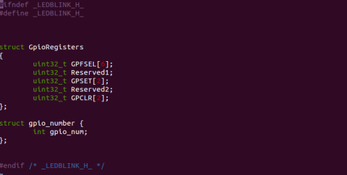
Here i am adding blinkled.h in the same directory. The below image will provide you more details about contain of file.

Header file for led blink driver

Header file for led blink driver

Include this header file in board file for raspberry pi. Add the below code in board file.

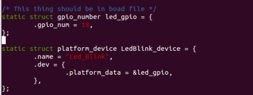
Defining a device in board file

Defining a device in board file

Here, i am declaring device named “LED_Blink” which has gpio number as a platform data on which it is connected.

Its time to register this declared device. In board file, bcm2708_init is a function which register all the peripherals devices with the kernel.

So, in this function we need to registered our device with the kernel platform bus.  Add the below line in in bcm2708_init function which register our device(“LED_Blink”) with kernel.

This device is added as platform device. I am not going in to much details of platform device, explanation can be found here.

Registration of Drivice

Registration of Device

At this stage we have registered our Led_Blink device to Linux kernel virtual bus. Now its time to write a driver for “Led_Blink” Device.

Writing driver for LED Blinking device

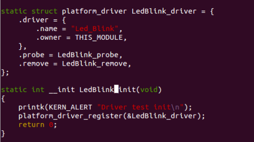
In the driver file, we need to declare one driver and register it with the kernel virtual bus with the same name which we gave to register device(“Led_Blink”). Linux kernel will compare the name of device and driver which is available on virtual bus and call the probe function of same driver. This is the basic concept of platform bus which is explained in the previous post.

Registration of Driver

Registration of Driver

Here, driver is declared with the  probe and remove function. Important thing is the name of the driver which is same as the device which we declared in device( In board file). Init function is the first function, which will be called on the successfully insertion of driver in the kernel. In our init function we have registered the platform driver to the bus.

On availability of the same device on the bus, kernel will calls the probe function of the same driver. So, after init function, probe will get called by the Kernel subsystem. Basically, probe will do all the initialization of device(GPIO) .

According to the BCM2835 peripheral  manual, the GPIO pins can be controlled by first configuring them as output by writing to one of GPFSELx registers and then writing to GPFSETx/GPFCLRx registers. We will define a structure describing the GPIO registers and provide functions for controlling GPIO pins using it.

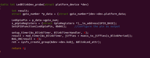
Probe routine of LED blink driver

Probe routine of LED blink driver

Above snippet shows the body of probe function. In the probe function, there are three impotent things  are done.

1. Configure Pin as GPIO

The below snippet shoes the routines for set pin functionality and set output value of pin.  This functions uses the structure pointer to access the registers of SoC.

Gpio Routines

Gpio Routines

2. Setup time for On and Off timing of LED

When timer elapse, state of pin will get changed and again timer will be re initialized from timer subroutine. The snipped below shows the body of time handler.

This subroutine causes the blinking of the LED.

Timer handler subroutine

Timer handler subroutine

3. Register /sys interface  to change blink period from user domain

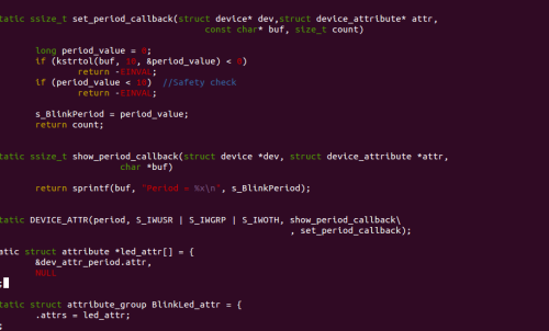
Sys interface is used to change the blinking period from user space. From the probe function BlinkLed_attr is registered for sys interface which has only one attribute name “period”.  User can get and set time interval using this interface. s_BlinkPeriod variable is used to store blanking period. The snippet below shows the subroutines for same.

Sys interface routines

Sys interface routines

You can download full driver code from here.

You have to add this add this module to linux source code. Here are the steps to do that.

Now, its time to compile your tweaked kernel using the steps shows above. Repeat from steps #5.

Enjoy your driver  !!!

21 Comments

Filed under Linux Device Driver

The vim Features You Probably Aren’t Usingm

Today i gonna show you some of beautiful features which will enhance programmers efficiency.  If you know basic usage of vim but think you may be missing some of essential features of GUI based editor in vim, these page is for you.

1. Word Suggestion

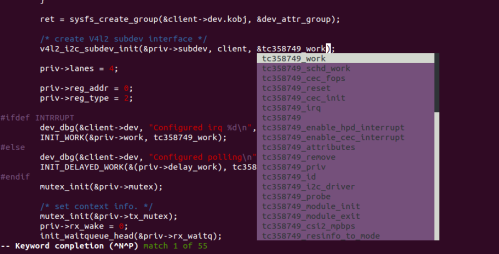
Writing programs some times you need suggestion of variable/function name from IDE. This is possible from vim. In insert mode, type the first couple of characters of a word, then press:

  • Ctrl-N to insert the next matching word;
  • Ctrl-P to insert the previous matching word.

As being programmer, this is  very useful when you are  entering the names of variables in a program.

Any word completion

Any word completion

Incidentally, if you really want CTRL-P or CTRL-N to scan a dictionary file, then try :set dictionary=/usr/. Multiple dictionaries can be used as well.

2. Find next/previous occurrence of word under cursor

Some times it is very useful if you can find next or previous occurrence of word in your file. This is possible from vim. In command mode, hit ‘#’ or ‘*’. In command mode, press ‘*’ or ‘#’  to find previous or next occurrence of the word which is under cursor.

 3. Undo  recent changes

To undo the changes ‘u’ command is used. In command mode, hitting ‘u’ will undo most last change.

4. % key

This is really awesome feature for programmers. The % key can be used for the following:

  • To jump to a matching opening or closing parenthesis, square bracket or a curly brace: ([{}])
  • To jump to start or end of a C-style comment: /* */.
  • To jump to a matching C/C++ preprocessor conditional: #if, #ifdef, #else, #elif, #endif.

In command mode, press ‘%’ to find the matching brace/comment/preprocessed of brace which is under cursor.

5. Repeat previous action

The “.” command repeats the last change made in normal mode. For example, if you press dw to delete a word, you can then press . to delete another word.

6. Open multiple windows in vim

It is a basic requirement of any programmer if to open multiple file concurrently. Vim supports this too.

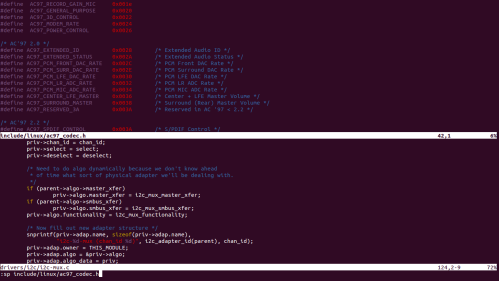
Vim’s ability to split its window into multiple panes using the “:sp" or “:vsp" commands.

To open a different file in a new split you can specify the filename as part of the command. For Horizontal split “:sp <filename>” is used and for vertical split “:vsp <filename>” is used.

Horizontal split

Horizontal split

Vertical split

Vertical split

To move cursor from one window to another window “CTRL+w CTRL+w” is used in normal mode.

This will change active file in round robin manner.  “CTRL+w <arrow key>” is also used to move the

cursor from one window to another window.

7. Open same file in split window

Some time there are certain need to to open same file in another split window. to do this in normal mode “CTRL+W v” and “CTRL+w s” is used to open same file in vertical and horizontal split of presently opened file.

8.  Set abbreviation

Abbreviations are just short cuts, you type which expands to normal version of them self. Vim provides a flexibility to defile new abbreviations. In normal mode, command “ab” is used to set new abbreviations.

To defile new abbreviation:

:ab def #define

Now, when you type the abbreviation in vim, as soon as  you hit space bar it will be expanded to the fill text.So by the typing of “def” in file, vim will expand this to “#define”, which can makes programmers life easier.

9. Open file under cursor

Often a file contains the name of a second file, and you would like to open the second file. In this condition,  “gf” command can help you a lot. On the “gf”command, vim will recognize file name and find same file name in path. When the cursor is on a local variable or function, this command will jump to its declaration. To retrun to previous file/cursor location CTRL+o is used.

10. Execute terminal command from vim

While using vim sometimes you will feel, you need to close the file(vim) and execute commands in terminal.In this post I will tell how to  execute commands inside vim without closing the file.

Now you are inside the vim editor has opened somefile.

Press ESC: and type ! command ,Output of the command will be listed in terminal and after pressing the enter again you will be redirected to text editor.

Syntax: ESC:! COMMAND

Execute shell commands without closing vim

Execute shell commands without closing vim

The above image shows syntax fro executing ls command on shell through vim.

11. View file in hex mode

Many firmware developer needs to view file in hex mode. vim gives a great feature to switch to hex mode when editing a file.

To enter in to hex mode, open a file in vi as usual, hit escape and type :%!xxd to switch into hex mode

To come out of hex mode hit escape again and type :%!xxd -r to exit from hex mode.

Feel Free to ask if you have any doubt !

Leave a comment

Filed under vim