Category Archives: Uncategorized

Device driver to interface shift reg with Raspberry pi 2

Hello Folks, after a long time my schedule allowed me to write some thing.

Today i am going to explain you the way to interface the shift register  with Linux based raspberry pi 2 board.  The shift register is the sequential logic which can used for data storage/parallel to serial conversation/ parallel to serial conversation. Hardware based stack can be constructed using several shift resister.

Shift registers are broadly distinguished in two types.

  1. Serial in, parallel out (SIPO):  In this configuration data is serially inserted in to shift register and output will be in form of parallel data bits. This is register used when more output ports are needed then available. This allows several binary devices to be controlled using only three pins, the binary controlled devices are attached to the parallel outputs of the shift register, then the desired state of all those devices can be sent out of the microprocessor using a single serial connection.
  2. Parallel in, serial out(PISO):  In this configuration parallely inserted data to shift register and output will be serial stream of bits. This configuration used to add binary inputs and give it in single stream to process. In this less micro-controller  pins are required to read the data.

This tutorials demonstrate how to interface SIPO  shift register (sn74hc595) to the raspberry pi 2. In addition to this, it explains how to write Linux device driver to control this hardware.

The sn74hc595 has an 8 bit storage register and an 8 bit shift register. Data is written to the shift register serially, then latched onto the storage register. The storage register then controls 8 output lines. Lets examine the ping configuration of sn74hc595 first. That will give us understanding about “How to drive sn74hc595 ? “.

Top_view

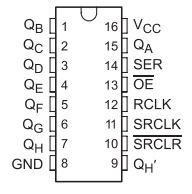
Ping configuration of sn74hc595

sn74hc595 register has 18 pins. which is shown in the image at left. Pin 16 is for VCC, which should be connected to 5v. Pin 8 is connected to common ground in the system. Pin number 1 to 7 and 15 is parallel data output pins.  Pin 14 is the serial data input pin.  Pin 11 is serial clock pin. when pin 11(SRCLK) goes from Low to High the value of pin 14(SER) is stored into the shift register and the existing values of the register are shifted to make room for the new bit. Pin 12 (RCLK) is used for latch. This pin should be low when data is written in the sift register. When it goes High the values of the shift register are latched to the storage register which are then outputted to pins Q0-Q7.  Pin 13 is to enable output. All latch output is enable if this pin is set to low.  Pin 10 is use for clear the output state on pins. Output pins will be cleared if low to high pulse is given to this pin. Default value of pin 10 is high.

How to co

So to drive this register, we need to control 5 pins.  Pin # 14,13,12,11 and 10. We need to connect output pins to LEDs  to check output of shift register. Based on this, we have derived a circuit diagram.
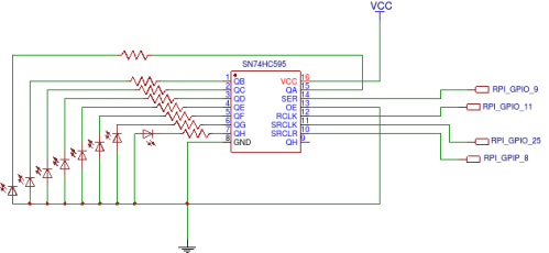
First-schamatic

Circuit diagram

Above image shows circuit diagram. Here we are using GPIOs of raspberry pi to control shift registers. RPI GPIO 9 is used as serial data line when is connected to SER(pin 14) of sn74hc595 . RPI GPIO 11 is used as latch clock line which is connected to RCLK (pin 12) of sn74hc595. RPI GPIO 25 is used as serial clock line which is connected to SRCLK (pin 11) of sn74hc595.  RPI GPIO 8 is used as serial clear line which is connected to SRCLR(pin 10) of sn74hc595. In addition to this, it is essential to connect VCC ad 5v and Common Ground with RPI.

Now, its time to design driver to control these GPIO pins. Driver will expose sysfs interface to change value represented by leds. Value which is written to this sysfs file will be represented by leds which is connected with sn74hc595.

So, lets start understanding responsibilities of init function of driver. As part of initialization of this driver, we need to Configure pin 21, 22,23 and 24 as GPIO which corresponds to GPIO 8, 9, 25 and 11.  In addition to this, we have to resigter sysfs class and device to control shift register.

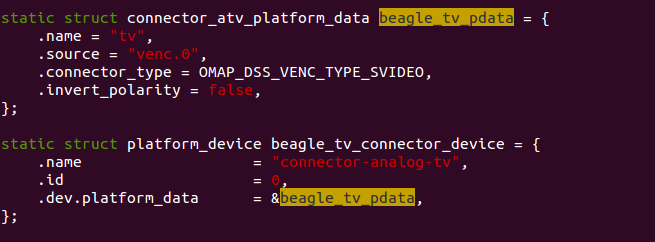
Les take a deep dive  into source code of driver.  As first part we have declared to global GPIOs pins which can be used in all driver code. As per our circuit design above we have declared the pins which is shown in below code snippet.
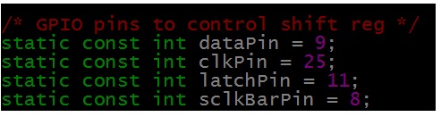
declatation of GPIO

GPIO Declaration

As part of initialization we have to configured this pins as GPIO pins. Below code snippet configures and request this pings as GPIO. The below snippet is part of init function of driver.

requrst_GPIO

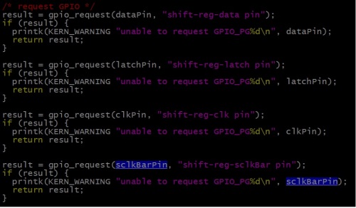
Configure Pings as GPIO

Now we have to configure this pins as output pins and set to appropriate default value.  As explained above we need to configure Pin 10(serial clock bar) to high.  The default value of all other pins will be low. The below snippet shows this.

op

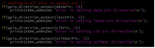
Configure GPIOs as output

Lets register sysfs interface to control output of shift register.  I have created new sysfs class and device to represent shift resister.

sysfs

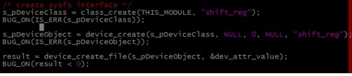
Registration of Sysfs interface

Every device interface in sysfs has attributes which can be read or write. Corresponding read write function registered with the attribute will get called when read or write operation performed on the this interface. Below snippet shows the registration of attribute named value with set and get value callback.

The attribute name should be the same as given by the time of creating file. Here we have given name as dev_attr_value. So out attribute is the value for which we have registered set and get routine. when we tried to read the file(sysfs Interface) from application, get_value_callback will be triggeres in the driver. In case we tried to write some value to file(sysfs Interface) from application,  set_value_callback will be triggers with the value to write in shift register.

attribute

Registration of sysfs device attribute

On low to high transmission of clock pulse,  internal register(storage register) value will shift by one and value on data pin will be moved to LSB of internal register. At the end after 8 bit data is shifted to the shift register,  by providing the latch pulse from low to high, all data from the internal register(storage Register) is latched to shift register pins. We have connected LEDs to the output pins of shift register.  This is shown by below snippet. To write some value to shift register,  it is essentials to put that value on data pin of shift register and then provide a clock pulse. On this clock pulse, data on internal register gets shifted and adds new bit(which is present on data pin) at the end presently shifted data.  So here in code, I am setting bit by bit this new_value variable on data pin and after setting one bit providing clock pulse. At the end i am providing the latch pulse so the 8 bit value which stored in the internal storage register will be  latched to the pins.

set_attribute

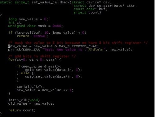
Routine to set value

When user application tries to  read the value from the sysfs interface, the get_value_callback will get called.  The callback will return old_value which was updated by the get value callback. The below snippet shows that. get_attribute

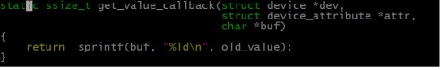
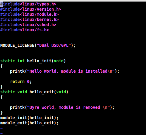
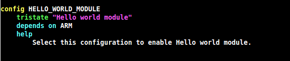
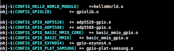
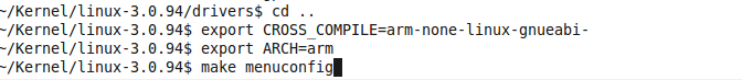
Here you can get full code for this driver. you can follow this steps to add module to Linux kernel source code and compile it.

Cheers !!!

Leave a comment

Filed under Linux Device Driver, Uncategorized

The story of device tree for platfrom device….

The whole story starts from non discover-able devices in the system. This post will provide you information about non discoverable devices as well it will provide you one of way of Linux kernel to deal with it. The second and fresh way is device tree.

Kernel starts, it has to initialize the drivers for the devices on the board. But often on embedded systems, devices can’t be discover at running time(i2c, spi, etc.). In this case, the Linux kernel has a c (board file) file that initialize these devices for the board. The below image shows structure for non discoverable devices and platform data for same. This will be registered with the virtual bus named platform bus and driver will also register it self with platform bus with the same name.

In this method,  kernel must be modified/compiled for each board or change in hardware on board.  Kernels are typically built around a single board file and cannot boot on any other type of system. Solution of this situation is provided by “Device tree”. A device tree is a tree data structure with nodes that describe the physical devices on the board. While using device tree, kernel no longer contains the description of the hardware, it is located in a separate binary blob called the device tree blob. The device tree is passed to the kernel at boot time. Kernel reads through it to learn about what kind of system it is. So on the change of board only developer needs to change device tree blob and that it new port of kernel is ready.

Platfrom device

Platform device

Here, you will get a good article on device tree format. It is recommended to go through it first at this stage.

Platform devices can work with dtb enabled system with out any extra modification. If the device tree includes a platform device that device will be instantiated and matched against a driver. All resource data will be available to the driver probe() in a usual way. The driver dose now know wither this device is not initialized with hard-cored. in board file.

Every device in the system is represented by a device tree node. The next step is to populate the tree with a node for each of the devices. The snippet below shows the dtb with node name “ps7-xadc”.  Every node in the tree represents a device, which must have a compatible property. compatible is the key using which an operating system uses to decide which device driver to bind to a device. In short compatible(ps7-xadc-1.00-a) specifies the name of the platform device which will get registered with bus.

Platform device in DTB

Platform device in DTB

On other side, in device driver when platform deriver structure is declared, it stores a pointer to “of_device_id”. This is shown by the below snippet. This name should be same which was given in the dtb file.  Now, when driver with name of “ps7-xadc-1.00.a” will get register with the platform bus, probe of that driver will get called.

Platform driver registration

Platform driver registration

The below snippet shows the probe function of the driver. In the probe, function platform_get_resource() provides property described by “reg” in dtb file. In our case base address of register set(0xf8007100) for hardware module and offset from the base address(0x20)  can be retrieved. Using which driver can request the memory region form the kernel. As same, function platform_get_irq() provides the property which id describe by “interrupts” in dtb file.

Getting device specific data

Getting device specific data

After garbing all details from dtb file, probe will register device as a normal way.  This is very straight forward procedure using which platform drivers work with device trees. As a result of this,  no need to declare platform_device in board file.

Cheers !!!

4 Comments

Filed under Device tree, Linux Device Driver, Platfrom device, Uncategorized

Virtualize(Emulate) your raspberry pi on windows…

Today, I am gonna talk about emulation of raspberry pi on windows.

This post is for specifically windows lovers 🙂

What is emulator ?

As wiki states, An emulator is hardware or software or both that duplicates (or emulates) the functions of one computer system (the guest) in another computer system (the host), different from the first one, so that the emulated behavior closely resembles the behavior of the real system (the guest).

It means that, virtual raspberry pi environment will be set up. Using which we can develop and test any application when Raspberry pi is not to hand, or when it’s not convenient or possible to power it up.

Here, in this post i am explaining to do this in four easy steps.

1. Get ARM emulator for windows

Raspberry pi has a ARM 11 based SoC. Open source processor emulator QEMU has a support for ARM architecture.  The QEMU site itself does not have a Windows binary download. Some one(Eric Lassauge) has tweaked qemu for windows. You can get latest qemu from here.

Extract the ZIP file to a folder on your PC.

2. Get kernel for raspberry pi with Qemu support

Here, are the steps to compile Linux kernel with qemu support.

To escape this step toy can just download the pre-compiled image from here.

Move this file to the QEMU folder which is created in previous step.

3. Get any of Raspi distro image

I am using the raspian “raspbmc” image. You can download this image from raspberry pi site.

Extract the file and put it in qemu folder.

4. Finally launching the emulator

Now, its time to launch the emulator with your kernel and disc image. The below command has to be hit on dos prompt on windows.

To do that, press Window button, search cmd in search bar. You will get one application named “cmd”. Open that application to write command. This is basically Dos prompt. The below image will provide you more information about it.

Finding cmd prompt in windows 7

Finding cmd prompt in windows 7

So, navigate to the directory where you have extracted qemu and all downloaded binaries.

Hit the below command to start qemu-arm for raspberry pi. In my case, i have kernel-qemu (which is downloaded in step #2) is the kernel for raspberry pi and raspbmc.img (which is downloaded in step #3)  is the image of file system.

qemu-system-armw.exe -M versatilepb -m 256 -cpu arm1176 -no-reboot -serial stdio -kernel kernel-qemu -hda raspbmc.img -append “root=/dev/sda2 panic=1”

The break down of the above command is :

1)  qemu-system-armw : the command to emulate an arm system on windows

2) -M versatilepb : the machine we need to emulate

3)  -m 256 : the amount of memory set that this version of the R-Pi has (The maximum memory size you can specify is 256Mb – that’s a limitation of QEMU for this hardware emulation – it may not work if you specify more)

4) -cpu arm1176 : the cpu we need to emulate

5) -no-reboot -append “root=/dev/sda2 panic1” : we mount our root filesystem to /dev/sda in the emulated R-Pi

installation of raspBMC

installation of raspBMC

First time,qemu will run raspbmc setup  and configure it accordingly. After setup, u will get command prompt of raspbmc.

rpi shall

rpi shall

And thats it !!!

you are done with your virtual raspi configuration.

6 Comments

Filed under Uncategorized

Add new module to Linux kernel source code

Kernel modules are pieces of code that can be loaded and unloaded into the kernel upon demand. They extend the

functionality of the kernel without the need to reboot the system. If you want to add your code(module) to a Linux

kernel, the most basic way to do that is to add your source files to the kernel source tree, add entry of your module in

appropriate Makefile and Kconfig file  and recompile the kernel. In fact, the kernel configuration process consists

mainly of choosing which files to include in the kernel to be compiled. All the device drivers are written using these

loadable modules.Let us add a very basic sample kernel module. Add this file to drivers/gpio directory in Linux kernel

source tree.

vim ./drivers/gpio/helloWorld.c helloWorld

helloWorld.c

helloWorld.c

Now we need to add configuration setting, so that we can add or remove this module from the By the time of Linux

kernel configuration(You can configure it from “make menuconfig”).  To do that add your modules entry in ./driver

/gpio/Kconfig file. Add below codes to ./drivers/gpio/Kconfig file.

vim ./drivers/gpio/Kconfig

vim ./drivers/gpio/Kconfig

Line 1 is the macro with using which our module can be configured.Line 3 states that this option can only be enabled if

CONFIG_ARM is enabled . Next We have to inform kernel to compile hello_world.c when HELLO_WORLD_MODULE

configuration is enabled.Add this to ./drivers/gpio/Makefile.

vim ./drivers/gpio/Makefile

vim ./drivers/gpio/Makefile

We have successfully added a new module to Linux kernel. Now lets test our new module with Linux kernel.To do that

first we need to give tool chain name to CROSS_COMPILE flag and architecture name to ARCH flag in Linux terminal.

Compilation process

Compilation process

Now configuration menu will appear. Navigate to Device Drivers—>GPIO Support —>Hello World Module  and enable

it. Now start compiling kernel and modules.

Your module will get inserted as a part of kernel.

Enjoy !!!

17 Comments

Filed under Uncategorized